Zenith work together with the famous laboratory in China to design and deliver the gold leaching plant. It help the mine factory to extract a major part of the residual gold contained in gold ore or some tailings. Here is the brief introduction of this very popular gold ore processing technology in the world. We do beleive that your gold ore processing business will be more sucessful by choosing Zenith.
1. The CIL process technology.
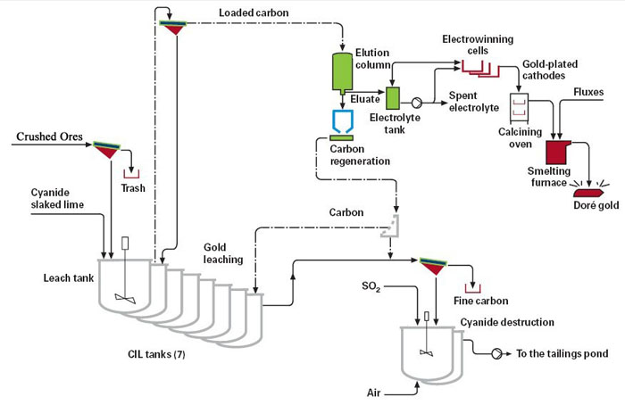
The ore is ground and concentrates are produced by means of conventional flotation and gravity circuits. The flotation tailings containing the unrecovered gold from the primary circuits are directed to the leaching plant and dissolved in an aerated sodium cyanide solution. The solubilized gold is simultaneously adsorbed onto coarse granules of activated carbon directly in the pulp in the so-called Carbon-In-Leach process (CIL). The loaded carbon is treated at high temperature to elute the adsorbed gold into the solution once again. The gold-rich eluate is fed into an electrowinning circuit where gold and other metals are plated out onto cathodes of steel wool. The loaded steel wool is pretreated by calcination before it is mixed with fluxes and melted. Finally, the melt is poured into a cascade of molds where gold is separated from the slag as gold bullion.
The CIL process utilizes safe and reliable technology and provides flxibility on raw materials analysis. It requires low inventory of precious metals. In addition, it ensures short processing time and low operating costs.
The Main features of the CIL system:
1. CIL tanks
The leach circuit comprises eight stainless steel tanks in series, located outdoors. Each tank is equipped with an agitator. The first tank is a pure leach tank and the following seven are CIL tanks. The flotation tailings slurry is pumped to the fist tank via a trash screen. Sodium cyanide, slaked lime slurry and air are added into the tanks. The slurry flws from tank to tank by gravity and gold is leached into the solution by cyanide and oxygen. Lime is added to the leach circuit to maintain a high pH of the slurry. This minimizes the formation of hydrogen cyanide.
2. Carbon adsorption The solubilized gold is adsorbed onto coarse granules of activated carbon in the tanks at the same time as the slurry flws from the fist CIL tank to the last. The carbon is retained in the tanks by using cylindrical, mechanically swept interstage screens, which are submerged in the pulp. The aperture of the interstage screens allows the leached pulp to pass through by gravity. The activated carbon is advanced counter-current to the slurry flw by pumping a portion of the slurry upstream with airlifts. A high grade of gold on the carbon and a high gold recovery are obtained by stage-wise adsorption and a counter-current flow. The carbon in the first CIL tank thus contains the highest grade of gold.
3. Carbon elution
Loaded carbon from the fist CIL tank is transferred by a slurry pump to the loaded carbon screen. The slurry is screened, the oversize carbon washed and gravitated to the vertical elution column. Here the carbon is washed with dilute hydrochloric acid to remove for instance soluble salts. The carbon is further rinsed with water to remove the acid before it is soaked with a caustic sodium cyanide solution at elevated temperature. A number of bed volumes of hot water are then pumped through the bed of carbon to eluate the gold. The gold-containing eluate is collected in the electrolyte tank.
4. Carbon regeneration
Not only gold is adsorbed onto the activated carbon, but a number of organic components, such as oils and flotation reagents, are accumulated within the porous structure of the carbon, blocking the active surface. A major part of the organic species remains on the surface after the elution process. The carbon also loses activity during the adsorption of gold and other species. In order to restore the active surface and to enable the reuse of carbon in the CIL circuit, it undergoes thermal regeneration. This is done in a gas-heated horizontal kiln at 650º, under a steam atmosphere.
5. Electrowinning
The gold-rich solution from the elution process, the electrolyte, is circulated through three parallel electrowinning cells over a period of 16–24 hours. Gold and other metals are precipitated on steel wool cathodes, which are submerged in the circulating electrolyte. At the anodes, oxygen is formed and degradation of cyanide occurs. The barren electrolyte is pumped to the process for reclamation of residual gold and to recover cyanide and sodium hydroxide.
6. Calcination and smelting
The loaded steel wool cathodes are transferred to an electrically heated calcination furnace. Iron and base metals are oxidized by air at about 750º. The obtained calcine is smelted together with flxes in a gas-heated furnace. Finally, the melt is poured into a cascade of molds where gold is separated from the slag as doré bullion. The oxidized impurities are present in the slag, which flats on the molten gold. The gold content in the final products is depending mainly on the gold-to-silver ratio in the calcine. Silver follows gold through the process.
7. Cyanide destruction
The barren pulp from the CIL circuit and any cyanide containing spillage are pumped to the cyanide destruction circuit via a carbon safety screen, to detect any leakage of carbon from the last tank. The barren pulp is combined with the non-cyanide-containing tailings from the parallel flotation circuit. The residual cyanide content is destroyed in two reactors by means of the INCO/SO2/Air process before it is pumped to the tailings pond. Cyanide is oxidized to cyanate by adding air, sulphur dioxide and lime in the reactors. Copper sulphate is also added when required. Cyanate and weakly soluble salts of cyanide are precipitated. Cyanate slowly decomposes in the tailings dam to nitrite, nitrate and nitrogen via formation of ammonia/ammonium. Residual-free cyanide and nitrogen compounds in the efflent are negligible and do not have any impact on the environment.
8. Dressing Test:
Like all the other mineral ore pcoessing plant, the gold ore processing plant should be designed base on the dressing test to fix the dressing index for the whole plant include such as the particle size, pulp density, reagent type and dosage, pickling time, desorption temperature, etc. Here is the datas after dressing test we fixed for this plant. 5). Any pulp collected inside the bunds or in the emergency pond can be pumped back to the CIL or destruction circuit. Bunds are present around all equipment where there are risks of cyanide solution leakage and they make it possible to collect and pump solutions back to the process.
Gold ore Carbon-In-Leaching (CIL) processing technology index
| Crushing and Grinding Sections | Feeding size | <200 mm | Remark | Pickling | Total pickling time | 6 h | |
| Particle Size | 75μ (D80) | Electrolyte System | Desorption temperature | 150 ℃ | |||
| Feeding Concentraion of Thickner | 16-17% | Desorption Pressure | 0.03-0.35MPa | ||||
| Thickner | Flocculant | 0.30% | Prepared Concentration | Stripping liquid | 1% | NaOH | |
| 0.03% | Fortified Concentration | 0.50% | NaCN | ||||
| Bottom flow concentration | 55% | Desorption Time | 9.5h | ||||
| CIL System | Pulp Desnity | 40-45% | adsorption time | 24h% | Electrowinning System | Voltage | 2.5V |
| Cyanide concentration | 0.05-0.12% | pH | 10.5 | Current | 50A/p | ||
| Leaching Time | 24h | Carbon intensity | 10g/l | Cathode bristles | 450g/p |
9. Safety and security
1). Cyanide has to be handled with caution. It is delivered to the plant in bigbags, packed in wooden boxes in sealed steel containers, and stored in a locked area located in the reagent storage building.
2). It is important to maintain a high pH value in the cyanide leaching process to minimize the formation of hydrogen cyanide. The pH is monitored by on-line measurements and controlled by the addition of slaked lime slurry. Too low a pH in the tanks will set off an alarm. The on-line pH probes are calibrated and checked against portable pH meters on a regular basis.
3). Equipment located indoors is covered and well ventilated where there is a risk of a high concentration of hydrogen cyanide. Ventilation gases are cleaned in a wet caustic scrubber system at high pH before they are vented off to the atmosphere. A small volume of cyanide containing scrubber solution is regularly diverted to the CIL circuit and replaced by an equal volume of fresh caustic solution. The ventilation system is also connected to an emergency power supply system.
4). All leaching tanks are located outdoors on a concrete foundation constructed with bunds, which can contain any pulp leakage from the tanks. The bunds also protect the tanks from accidental damage from loaders and other vehicles. The foundation overflws to an emergency pond and is heated to keep the flor inside the bunds free from ice and snow during the winter period.
5). Any pulp collected inside the bunds or in the emergency pond can be pumped back to the CIL or destruction circuit. Bunds are present around all equipment where there are risks of cyanide solution leakage and they make it possible to collect and pump solutions back to the process.